Modius Data Center Blog

Visualize Data Center Site Performance

Posted by Jay Hartley, PhD on Wed, Jul 06, 2011 @ 07:19 PM

There has been plenty of discussion of PUE and related efficiency/effectiveness metrics of late (Modius PUE Blog posts: 1, 2, 3). How to measure them, where to measure, when to measure, and how to indicate which variation was utilized. Improved efficiency can reduce both energy costs and the environmental impact of a data center. Both are excellent goals, but it seems to me that the most common driver for improving efficiency is a capacity problem. Efficiency initiatives are often started, or certainly accelerated, when a facility is approaching its power and/or cooling limits, and the organization is facing a capital expenditure to expand capacity.

When managing a multi-site enterprise, understanding the interaction between capacity and efficiency becomes even more important. Which sites are operating most efficiently? Which sites are nearing capacity? Which sites are candidates for decommissioning, efficiency efforts, or capital expansion?

For now, I will gracefully skip past the thorny questions about efficiency metrics that are comparable across sites. Let’s postulate for a moment that a reasonable solution has been achieved. How do I take advantage of it and utilize it to make management decisions?

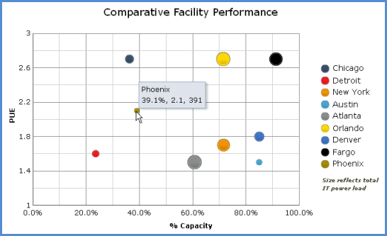
Consider looking at your enterprise sites on a “bubble chart,” as in Figure 1. A bubble chart enables visualization of three numeric parameters in a single plot. In this case, the X axis shows utilized capacity. The Y axis shows PUE. The size of each bubble reflects the total IT power load.

Before going into the gory details of the metrics being plotted, just consider in general what this plot tells us about the sites. We can see immediately that three sites are above 80% capacity. Of the three, the Fargo site is clearly the largest, and is operating the most inefficiently. That would be the clear choice for initiating an efficiency program, ahead of even the less-efficient sites at Chicago and Orlando, which are not yet pushing their capacity limits. One might also consider shifting some of the IT load, if possible, to a site with lower PUE and lower utilized capacity, such as Detroit.

Data Center, Efficiency, Capacity

In this example, I could have chosen to plot DCiE (Data Center Infrastructure Efficiency)  vs. available capacity, rather than the complementary metrics PUE vs. utilized capacity. This simply changes the “bad” quadrant from upper right to lower left. Mainly an individual choice.

Efficiency is also generally well-bounded as a numeric parameter, between 0 and 100, while PUE can become arbitrarily large. (Yes, I’m ignoring the theoretical possibility of nominal PUE less than 1 with local renewable generation. Which is more likely in the near future, a solar data center with a DCiE of 200% or a start-up site with a PUE of 20?) Nonetheless, PUE appears to be the metric of choice these days, and it works great for this purpose.

Whenever presenting capacity as a single number for a given site, one should always present the most-constrained resource. When efficiency is measured by PUE or a similar power-related metric, then capacity should express either the utilized power or cooling capacity, whichever is greater. In a system with redundancy, be sure to that into account

The size of the bubble can, of course, also be modified to reflect total power, power cost, carbon footprint, or whatever other metric is helpful in evaluating the importance of each site and the impact of changes.

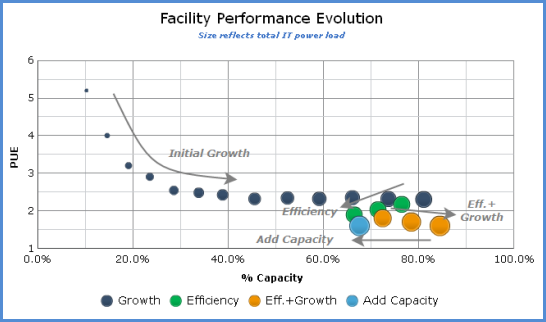
This visualization isn’t limited to comparing across sites. Rooms or zones within a large data center could also be compared, using a variant of the “partial” PUE (pPUE) metrics suggested by the Green Grid. It can also be used to track and understand the evolution of a single site, as shown in Figure 2.

This plot shows an idealized data-center evolution as would be presented on the site-performance bubble chart. New sites begin with a small IT load, low utilized capacity, and a high PUE. As the data center grows, efficiency improves, but eventually it reaches a limit of some kind. Initiating efficiency efforts will regain capacity, moving the bubble down and left. This leaves room for continued growth, hopefully in concert with continuous efficiency improvements.

Finally, when efficiency efforts are no longer providing benefit, capital expenditure is required at add capacity, pushing the bubble back to the left.

Those of you who took Astronomy 101 might view Figure 2 as almost a Hertzsprung-Russell diagram for data centers!

Whether tracking the evolution of a single data center, or evaluating the status of all data centers across the enterprise, the Data Center Performance bubble chart can help understand and manage the interplay between efficiency and capacity.

Data Center Capacity

Topics: Capacity, PUE, data center capacity, data center management, data center operations, DCIM

Measuring PUE with Shared Resources, Part 2 of 2

Posted by Jay Hartley, PhD on Wed, May 25, 2011 @ 05:02 PM

PUE in an Imperfect World

Last week I started discussing the instrumentation and measurement of PUE when the data center shares resources with other facilities. The most common shared resource is chilled water, such as from a common campus or building mechanical yard. We looked at the simple way to allocate a portion of the power consumed by the mechanical equipment to the overall power consumed by the data center.

The approach there assumed perfect sub-metering of both the power and chilled water, for both the data center and the mechanical yard. Lovely situation if you have it or can afford to quickly achieve it, but not terribly common out in the hard, cold (but not always cold enough for servers) world. Thus, we must turn to estimates and approximations.

Of course, any approximations made will degrade the ability to compare PUEs across facilities--already a tricky task. The primary goal is to provide a metric to measure improvement. Here are a few scenarios that fall short of the ideal, but will give you something to work with:

  • Calculate PUE pPUECan’t measure data-center heat load, but have good electrical sub-metering. Use electrical power as a substitute for cooling load. Every watt going in ends up as heat, and there usually aren’t too many people in the space routinely. Works best if you’re also measuring the power to all other non-data-center cooled space. The ratio of the two will get you close to the ratio of their cooling loads. If there are people in a space routinely, add 1 kWh of load per head per 8-hr day of light office work.
  • Water temperature is easy, but can’t install a flow meter. Many CRAHs control their cooling power through a variable valve. Reported “Cooling Load” is actually the percentage opening of the valve. Get the valve characteristics curve from the manufacturer. Your monitoring system can then convert the cooling load to an estimated flow. Add up the flows from all CRAHs to get the total.
  • Have the head loads, but don’t know the mechanical yard’s electrical power. Use a clamp-on hand meter to take some spot measurements. From this you can calculate a Coefficient of Performance (COP) for the mechanical yard, i.e., the power consumed per cooling power delivered. Try to measure it at a couple of different load levels, as the real COP will depend on the % load.
  • I’ve got no information about the mechanical yard. Not true. The control system knows the overall load on the mechanical yard. It knows which pumps are on, how many compressor stages are operating, and whether the cooling-tower fan is running. If you have variable-speed drives, it knows what speed they’re running. You should be able to get from the manufacturer at least a nominal COP curve for the tower and chiller and nominal power curves for pumps and fans. Somebody had all these numbers when they designed the system, after all.

Whatever number you come up with, perform a sanity check against the DOE’s DCPro online tool. Are you in the ballpark? Heads up, DCPro will ask you many questions about your facility that you may or may not be prepared to answer. For that reason alone, it’s an excellent exercise.

It’s interesting to note that even the Perfect World of absolute instrumentation can expose some unexpected inter-dependencies. Since the efficiency of the mechanical yard depends on its overall load level, the value of the data-center PUE can be affected by the load level in the rest of the facility. During off hours, when the overall load drops in the office space, the data center will have a larger share of the chilled-water resource. The chiller and/or cooling-tower efficiency will decline at the same time. The resulting increase in instantaneous data center PUE does not reflect a sudden problem in the data center’s operations; though it might suggest overall efficiency improvements in the control strategy.

PUE is a very simple metric, just a ratio of two power measurements, but depending on your specific facility configuration and level of instrumentation, it can be remarkably tricky to “get it right.” Thus, the ever-expanding array of tier levels and partial alternative measurements. Relatively small incremental investments can steadily improve the quality of your estimates. When reporting to management, don’t hide the fact that you are providing an estimated value. You’ll only buy yourself more grief later when the reported PUE changes significantly due to an improvement in the calculation itself, instead of any real operational changes.

The trade-off in coming to a reasonable overall PUE is between investing in instrumentation and investing in a bit of research about your equipment and the associated estimation calculations. In either case, studying the resulting number as it varies over the hours, days, and seasons can provide excellent insight into the operational behavior of your data center.

Topics: BMS, Dr-Jay, PUE, instrumentation, Measurements-Metrics, pPUE

Measuring PUE with Shared Resources, Part 1 of 2

Posted by Jay Hartley, PhD on Wed, May 18, 2011 @ 09:02 AM

Last week I wrote a little about measuring the total power in a data center, when all facility infrastructure are dedicated to supporting the data center. Another common situation is a data center in a mixed environment, such as a corporate campus or an office tower, at which the facility resources are shared. The most common shared resource is the chilled-water system, often referred to as the “mechanical yard.” As difficult as it sometimes can be to set up continuous power monitoring for a stand-alone data center, it is considerably trickier when the mechanical yard is shared. Again, simple in principle, but often surprisingly painful in practice.

Mixed Use Facility

One way to address this problem is to use The Green Grid’s partial PUE, or pPUE. While the number should not be used as a comparison against other data centers, it provides a metric to use for tracking improvements within the data center.

This isn’t always a satisfactory approach, however. Given that there is a mechanical yard, it’s pretty much guaranteed to be a major component of the overall non-IT power overhead. Using a partial PUE (pPUE) of the remaining system and not measuring, or at least estimating, the mechanical yard’s contribution masks both the overall impact of the data center and the impact of any efficiency improvements you make.

There are a number of ways to incorporate the mechanical yard in the PUE calculations. Full instrumentation is always nice to have, but most of us have to fall back on approximations. Fundamentally, you want to know how much energy the mechanical yard consumes and what portion of the cooling load is allocated to the data center.

Data Center Mechanical Plant

The Perfect World

In an ideal situation, you have the mechanical yard’s power continuously sub-metered—chillers, cooling towers, and all associated pumps and fans. Not unusual to have a single distribution point where measurement can be made. Perhaps even a dedicated ATS. Then for the ideal solution, all you need is sub-metering of the chilled-water going into the data center.

The heat load, h, of any fluid cooling system can be calculated from the temperature change, ∆T, and the overall flow rate, qh=Cq∆T, where C is a constant that depends on the type of fluid and the units used. As much as I dislike non-metric units, it is easy to remember that C=500 when temperature is in °F and flow rate is in gal/min, giving heat load in BTU/h. (Please don’t tell my physics instructors I used BTUs in public.) Regardless of units, the total power to allocate to your data center overhead is Pdc=Pmech (hdc⁄hmech). Since what matters is the ratio, the constant C cancels out and you have Pdc=Pmech (q∆Tdcq∆Tmech ).

You’re pretty much guaranteed to have the overall temperature and flow data for the main chilled-water loop in the BMS system already, so you have q∆Tmech. Much less likely to have the same data for just the pipes going in and out of your data center. If you do, hurrah, you’re in The Perfect World, and you’re probably already monitoring your full PUE and didn’t need to read this article at all.

Perfect and You Don’t Even Know It

Don’t forget to check the information from your floor-level cooling equipment as well. Some of them do measure and report their own chilled-water statistics, in which case no additional instrumentation is needed. In the interest of brand neutrality, I won’t go into specific names and models in this article, but feel free to contact me with questions about the information available from different equipment.

Perfect Retrofit

If you’re not already sub-metered, but you have access to a straight stretch of pipe at least a couple feet long, then consider installing an ultrasonic flow meter. You’ll need to strap a transmitter and a receiver to the pipe, under the insulation, typically at least a foot apart along the pipe. No need to stop the flow or interrupt operation in any way. Either inflow or outflow is fine. If they’re not the same, get a mop; you have other more pressing problems. Focus on leak detection, not energy monitoring.

If the pipe is metal, then place surface temperature sensors directly on the outside of the inflow and outflow pipes, and insulate them well from the outside air. Might not be the exact same temperature as the water, but you can get very close, and you’re really most concerned about the temperature difference anyway. For non-metal pipes, you will have to insert probes into the water flow. You might have available access ports, if you’re lucky.

The Rest of Us

Next week I’ll discuss some of the options available for the large population of data centers that don’t have perfect instrumentation, and can’t afford the time and/or money to purchase and install it right now.

Topics: BMS, Dr-Jay, PUE, instrumentation, Measurements-Metrics, pPUE

Latest Modius Posts

Posts by category

Subscribe via E-mail